FAQ
Here are answers to some of the most frequently asked questions related to wind loads.
Have any suggestions to share with WindLoad.Solutions and the community?
Please let us know by contacting us here.
The most recent publication is the ASCE 7-22.
Only the most recent version of the ASCE 7 should be used in determining or calculating wind load pressures and provided to your permitting department for approval.
Previous versions: ASCE 7-95, ASCE 7-98, ASCE 7-02, ASCE 7-05, ASCE 7-10, ASCE 7-16
WindLoad.Solutions applies the latest ASCE 7-22 publication for all wind load pressure calculations.
To know how much force (wind load pressure) it will take to over turn an entire building, or blow out the windows, doors, and roofs on a building.
Want to know more? Go to FAQ, "What do I do with the calculated wind load pressures?"
A wind load calculator is a tool, typically a program or software, that is used to apply the formulas provided in the ASCE 7 publication to determine wind load pressures. The programmer takes the provided formulas and applies algorithms to link all the formulas together to then obtain the proper calculations to provide the accurate wind load pressures.
If you live in the USA, the ASCE 7 publication is the only reference that should be used. Additionally, all permitting departments in the USA only accept and will only approve wind load pressures per the ASCE 7 publication.
Be leery of using free wind load programs. Free wind load calculator spreadsheets that are very basic, or taking shortcuts and applying methods not supported by the ASCE 7 can/will cause problems with you getting acceptance and approvals from your permitting department. As well, by taking shortcuts by using free wind load calculators, and relying on the inaccurate output to purchase windows, doors, shutters, skylights, etc...when you get rejected by the permit department due to inaccurate data, the potential is extremely high for cost overruns as your purchases for materials and costs for redoing structural design will negatively affect your budget.
Wind Load Solutions advice: It is worth paying on the front-end for accurate wind loads to support your purchase of materials and structural design, versus having to redo work. It will not only save you money, but it will also save you time (and time = money). It will also build your credibility with your clients and your permitting department.
The calculated wind load pressure tells the designer/engineer/architect what the limit is and what pressures need to be resisted. Whether it be the type of material used, the type or quantity of straps to hold the structure in place, or to simply know what windows, doors, shutters, skylight, etc. to purchase.
Example: When selecting windows from a manufacturer's catalog the windows have wind load pressure ratings. Based on the wind load pressures the customer will be able to identiy what windows are acceptable to meet code and permit requirements. This is also good for estimating costs, as stronger windows cost more.
The difference between Main Wind Force Resisting Systems (MWFRS) and Components & Cladding (C&C) wind load pressure calculations methods are as follows:
- MWFRS: Wind load pressures on entire building, to find what will overturn the structure.
- C&C: Wind load pressures on windows, doors, skylights, shutters, roofs.
Types of wind load pressures, or forces on buildings:
- Uplift Load – Wind pressures that cause lift.
- Shear Load – Horizontal wind pressures that cause tilt.
- Lateral Load – Horizontal wind pressure that can push and pull, with probability of turning over structure.
Per the ASCE 7 the "Effective Wind Area" is the area used to determine the wind load formula symbol (GCp).
GCp = product of the external pressure coefficient and gust-effect factor to be used in determination of wind loads for buildings.
For Components & Cladding elements, the effective wind area in Figs. 30.4-1 through 30.4.7, 30.5-1, 30.6-1, and 30.8-1 through 30.8-3 is the span of length multiplied by an effective width that need not be less than one-third the span length. For cladding fasteners, the effective wind area shall not be greater than the area that is tributary to an individual fastener.
Nominal Design Wind Speed is a reduction of the "Ultimate Design Wind Speed" by 40%. This is a 40% reduction of the Ultimate Design Wind Speed positive and negative pressures. Or you could also get the 40% reduction by entering in the Nominal Velocity and plug it into your wind load calculation formula. The way you calculate the Nominal Velocity is to multiply the Ultimate Velocity (found on the Velocity Maps provided by ASCE 7-10) by the square root of the value 0.6. As far as when to know if the Nominal Design Wind Speed is accepted, you will need to contact your county's permit department to make sure your structure can pass with a Nominal Design.
On our program, you can toggle between the Nominal and Ultimate Wind Speed Designs. You are required to enter in the Ultimate Velocity provided on the ASCE 7-10 Velocity Maps, and our wind load programs will automatically calculate the Nominal Velocity and the Nominal Design Pressures for you.
Wind Load Solutions uses Office 365 so you can access your ASCE 7-16 wind load calculator excel program online. Thus you have access to your wind load program from any device, anywhere you have an internet connection.
Yes, our wind load program uses Microsoft Excel spreadsheets to perform all the calculations.
Yes, algorithms are applied to take the user's input and apply them to all the formulas, figures and tables from the ASCE 7-16 to then provide the accurate wind load pressures and variable output.
Wind load calculations can be very tedious and time consuming. By using Wind Load Solutions' wind load analysis software a considerable amount of time can be saved.
ASCE 7-10 Wind Speed Map Updates
- The wind speed map for all locations has been revised and Importance Factors have been removed.
- There are 3 new wind speed maps. Wind speed maps are provided for each Risk Category as opposed to a single map with importance factors (300-year period, 700-year return period, 1700-year return period). The difference is that all of the previous ASCE 7 Standards had referenced only one wind velocity map for all Risk Categories.
- New wind speed maps have replaced the existing maps that are directly applicable for determining design wind pressures using the strength design approach. Different maps are provided for different Risk Categories instead of a single map with importance factors to be applied for each Risk Category.
- Wind speed values are now represented in the ASCE 7-10 as "Ultimate" wind speeds.
- Strength design level wind speeds replace the ASD level wind speeds.
- Comparative hurricane wind speeds are lower than those given in the ASCE 7-05.
- The wind speeds in the maps are much higher than those in previous editions; the Load Factor on "W" in Section 2.3.2 is now 1.0 instead of 1.6 as established in the ASCE 7-05.
- Importance Factors have been used in previous editions of the ASCE 7 to adjust the velocity pressure to different annual probabilities of being exceeded. However, the use of Importance Factors was an approximate means for adjusting the return period because the slope of the wind speed vs. return period curves differ. The distance inland where the hurricanes can influence wind speeds increases with the return period. This situation was not adequately addressed by using Importance Factors from a table.
Updates for Allowable Wind Speeds That Supersede Wind Speeds Provided in the ASCE 7-10
- The basic wind speed shall be increased where records or experience indicate that the wind speeds are higher than those reflected in Fig. 26.5-1 of the ASCE 7-10.
- Mountainous terrain, gorges, and special wind regions shown in Fig. 26.5-1 of the ASCE 7-10 shall be examined for unusual wind conditions. The authority having jurisdiction shall, if necessary, adjust the values given in Fig. 26.5-1 to account for higher local wind speeds. Such adjustment shall be based on meteorological information and an estimate of the basic wind speed obtained in accordance with the provisions of ASCE 7-10 Section 26.5.3.
- For areas outside hurricane-prone regions, regional climate data shall only be used in lieu of the basic wind speeds provided in the ASCE 7-10 Fig. 26.5- when (1) approved extreme-value statistical-analysis procedures have been employed in reducing the data; and (2) the length of record, sampling error, averaging time, anemometer height, data quality, and terrain exposure of the anemometer have been taken into account. Reduction in basic wind speed below that of Fig. 26.5-1 shall be permitted.
- In hurricane-prone regions, wind speeds derived from simulation techniques shall only be used in lieu of the basic wind speeds given in the ASCE 7-10 Fig. 26.5-1 when approved simulation and extreme value statistical analysis procedures are used. The use of regional wind speed data obtained from anemometers is not permitted to define the hurricane wind-speed risk along the Gulf and Atlantic coasts, the Caribbean, or Hawaii.
- In areas outside hurricane-prone regions, when the basic wind speed is estimated from regional climatic data, the basic wind speed shall not be less than the wind speed associated with the specified mean recurrence interval, and the estimate shall be adjusted for equivalence to a 3-second gust of wind speed at 33 ft (10 m) above the ground in Exposure C.
ASCE 7-10 Importance Factor Update
- In the equation for Velocity pressure (qz) the importance factor has been removed, and the coefficient 0.00256 (0.613 in SI) shall be used except where sufficient climatic data are available to justify the selection of a different value of this coefficient/factor for a design application.
ASCE 7-10 Category "D" Update
- Surface Roughness Category "D" now applies to all water surfaces including water surfaces in hurricane-prone regions.
ASCE 7-10 Updates for the State of Hawaii
- Entire State of Hawaii has its own special wind region.
- The reasoning behind this is due to the highly complex three-dimensional topography in the State of Hawaii. This conclusion was reached by numerous studies. The topography has speed-up effects that cannot be adequately portrayed by a single statewide value of wind speed nor at the macro-scale of a national map. The State of Hawaii has addressed this issue with the development of wind maps for each local jurisdiction.
- For these new "special region maps" for the State of Hawaii, you must reference the Hawaii State Building Code.
- Although the probabilistic reference wind speeds are provided for Hawaii in the ASCE 7-10, the intent is that the actual design wind speeds are to be further modified as determined from the authority having jurisdiction. Wind speeds are identified simply to provide the reference wind speed for each Risk Category, and also ensure that the wind-borne debris region criteria in the ASCE 7-10 is appropriately triggered by the net value of net effect wind value.
Reference: General Requirements for Determining Wind Loads & ASCE 7-10
First off, your building permit department will deny your information if it does not abide by the latest ASCE 7. Versions of ASCE 7-98 and lower are obsolete. They should not even be practiced. There have been major changes. Below are some major changes that would affect your design according to C&C.
- Method 1 has been modified. Roof slope calculations have been modified.
- Exposure A is no longer used.
- Parapet calculations were added.
- Permission to interpolate the exposure category for the surface roughness length parameter, using an acceptable/reasonable procedure.
The "Zones" are the locations on the walls and roof of a structure that identify the locations that have more pressure applied to them than other locations. The Zones that have the most pressure are the corner Zones of the walls (Zone 5) and the perimeter Zones of the roof (Zones 2 and 3). The interior Zone pressures do not have as much pressure applied to them as the corner and perimeter Zones. The interior Zone of the wall is Zone 4 and for the roof is Zone 1.
The value of "a" (which is automatically calculated for you in our program) will be your starting point. This value (a) is the horizontal dimension that provides you with Zone 5 for your walls and Zone 3 for (the corner of) your roof. You measure from the corner, inwards. For your walls, Zone 4 will be the remaining area between the Zones 5's measured from each corner, and for your roofs, Zone 2 will be the remaining area between the Zone 3's measured from each corner. Also, for roofs, Zone 1 is the entire area left over from Zones 2 and 3. Additionally for the roofs, you can divide up the areas for the Zones (1,2, and 3) to be the areas measured between your rafters; since this is the area between the tie-downs.
Below is a diagram that should help you visualize how to break up the zones.
Note:
- Zones 1, 2, and 3 are always applied to the roof.
- Zone 3: are the edge or corner sections; always equal to the value of "a".
- Zone 2: are the perimeter sections; minus the Zone 3 (edge/corner) areas.
- Zone 1: are the interior sections. Basically, the interior area left over after subtracting the areas of the Zone 3, and Zone 2.
- Zones 4 and 5 are always applied to the walls.
- Zone 5: are the corner sections; always equal to the value of "a".
- Zone 4: are the interior sections; or the area remaining after subtracting the Zone 5 sections.
- Remember: The Value of "a" is always applied to the roof and wall corners.
- Remember: Any door or window dimension that falls within the area of "a" (edge/corner = Zone 5) section must have the Zone 5 applied to it.
- Remember: Any opening dimension that falls with the area of "a" (edge/corner = Zone 3) on the roof (such as a sky-light) must have the Zone 3 applied to it.
Please reference the Terms of Service on the WindLoad.Solutions website as well as our disclaimer below.
By using the WindLoad.Solutions program, it is agreed that the user takes all responsibility for directors, officers, agents, and shareholders of the WindLoad.Solutions are not held responsible or accountable for design pressures and all calculated data taken from the WindLoad.Solutions program.
This program is not intended to replace the services of a professional engineer. This program is simply a tool to help process needed information quickly and accurately under the ASCE 7-16 Standard (ASCE 7) and the International Building Code (IBC). It is always good practice to consult a professional engineer in using this product.
This program is not responsible for information not included in the ASCE 7-16 publication.
With the purchase of this program, you have agreed to the use of this program for the use at one operating station/computer. Multiple use of an individual program is prohibited.
All sales are final at the time of purchase.
With the purchase of this program, you have agreed to follow the information written above.
This serves as a legal document.
The tributary area is a loaded area that contributes to the load on the member supporting that area.
How to Whitelist Email

Whitelisting an email means telling your email provider that you want to receive messages from a certain sender in your inbox, not in your spam or junk folder. This can help you avoid missing important emails that might get filtered out by mistake.
To whitelist an email, you need to know what is whitelist and how it works. A whitelist email address is one that you trust and want to hear from. By adding it to your whitelist, you tell your email provider to let it through to your inbox every time.
If you don't whitelist email senders, you might not get notified when they send you something important that you need to read. No matter what email provider you use, it's essential to know how to whitelist an email so that nothing gets lost or overlooked.
- Click the settings button (in the top-right corner of the screen), then select “Settings” from the resulting drop-down menu.
- Navigate to the tab labeled Filtered and Blocked Addresses to access information about your existing filters.
- Select Create a new filter and enter the emails or domains you want to whitelist.
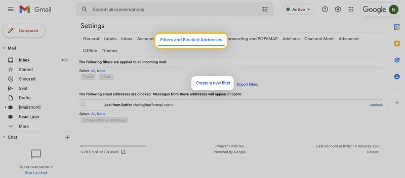
To whitelist a single email address, for example, type the entire address. On the other hand, if you’re trying to whitelist every sender from a certain domain, type the domain alone, such as “@windload.solutions”. This will tell Gmail to approve every message from windload.solutions.
- Click Create filter to approve the new filter, then mark Never send to Spam to whitelist every email within the filter. You can also choose to Star these emails, apply a given label, or mark them as important.
- Open the Gmail application.
- Navigate to Spam or Junk folder.
- Click on the message you wish to view.
- Select the option Report not spam.
- You will now receive messages from this sender as normal.
If you want to make sure you always get emails from a certain sender or website in Outlook.com, you can add them to a list called Safe senders. This means that even if your spam filters are very strict, you won't miss any messages from them. To do this, you need to enter their email address or domain name in the Safe senders group.
-
- Click on Settings, then View all Outlook settings.
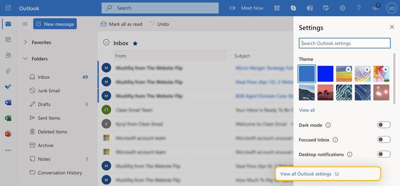
- Go to Junk email, then choose Safe senders and domains or Safe mailing lists to select the domain or email you want to whitelist.
- To add a domain name or email address to Safe senders, type it in the box. For domain names, don't forget the @ sign. This way, you'll only get emails from the exact domain name you entered, not any variations of it.
A faster and easier way to do the same thing is to just add the email address of the person who sent you a message to your Outlook Contacts. You don't have to type in any details yourself with this method.
Yahoo Mail makes it super easy to whitelist a sender or domain name. If you already got an email from them, just find it in the Bulk folder and click Not Spam. That's it! Yahoo Mail will remember your choice and let future emails from them go straight to your inbox.
But what if you haven't received any email from them yet? No worries, you can still whitelist them by following these steps:
- Navigate to Settings icon, then click More Settings from the Yahoo Mail menu.
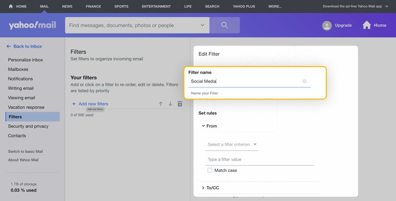
- Select Filters and hit Add new filters to enter information about the domain name or sender.
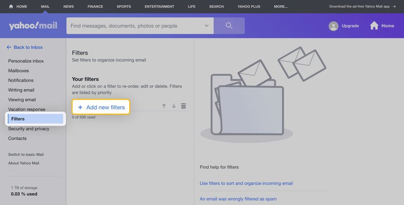
- This is where you can type any text that you want to allow in your future emails. It could be an email address or a domain name, or something that you think will be in the email content.
If you want to whitelist a domain name or email sender on Yahoo Mail, the easiest way is to do it after you get a message from them in your Bulk folder. So, you can ask them to send you a test email first and then whitelist them from there.
- Open Yahoo Mail Mobile App.
- Click on the sidebar.
- Click on the Spam folder.
- Find the email you wish to whitelist.
- Click Move and then click Inbox.
A common problem for people who want to whitelist emails on AOL is that AOL doesn't use a regular whitelist system. Instead, it trusts any email address that a user has saved in their address book. This means that the address book in AOL works like a whitelist for Gmail and Outlook.
Here are step-by-step instructions for whitelisting an email address in AOL:
- Log in to your AOL account.
- Open Contacts from the left navigation pane.
- Click the New Contact icon and enter the required information.
- Click the Add Contact button located at the bottom.
It's not hard to do this, and getting rid of contacts is just as simple. Just pick the contact you don't want and hit the Delete button on top of the page. If you want to make sure they can't email you again, you need to go to Options -> Mail Settings -> Spam Settings. There, you can put the contact on your email blacklist.
Zoho is designed for businesses, so it takes spam emails very seriously. Spam emails can trick you into giving away your personal or financial information, or infect your device with malware. That's why Zoho gives you powerful tools to block unwanted emails and make sure you receive the ones you need.
One of these tools is the Zoho whitelist, which lets you add an email address to a list of trusted senders. Here's how you can do that:
- Login to Zoho Mail.
- Go to Settings.
- Navigate to Anti-Spam List.
- Click on the Email Address tab and then click on Whitelist/Blacklist Emails.
- Click the Add new whitelist email field.
- Enter the address and press the Enter key.
If you want to keep your emails safe from prying eyes and annoying spammers, ProtonMail is a great choice. It has a strong encryption system that scrambles your messages so only you and the intended recipient can read them. Plus, it has a smart feature that automatically filters out junk mail and puts it in the spam folder.
But sometimes, the smart feature can be too smart and mark a good email as spam by mistake. That's why ProtonMail lets you whitelist email addresses that you trust. When you do that, ProtonMail will always deliver emails from those addresses to your Inbox folder. Whitelisting an email in ProtonMail is easy, and you can do it by following these steps:
- Log in to your ProtonMail account.
- Go to the Settings section.
- Click the Filters tab.
- Select ADD NEW FILTER under the Whitelist section.
- Enter the address and click SAVE.